- 您现在的位置:买卖IC网 > Sheet目录1991 > CS4361-CZZR (Cirrus Logic Inc)IC DAC STER 6CH 105DB 20-TSSOP
9
CS4361
Confidential Draft
9/30/11
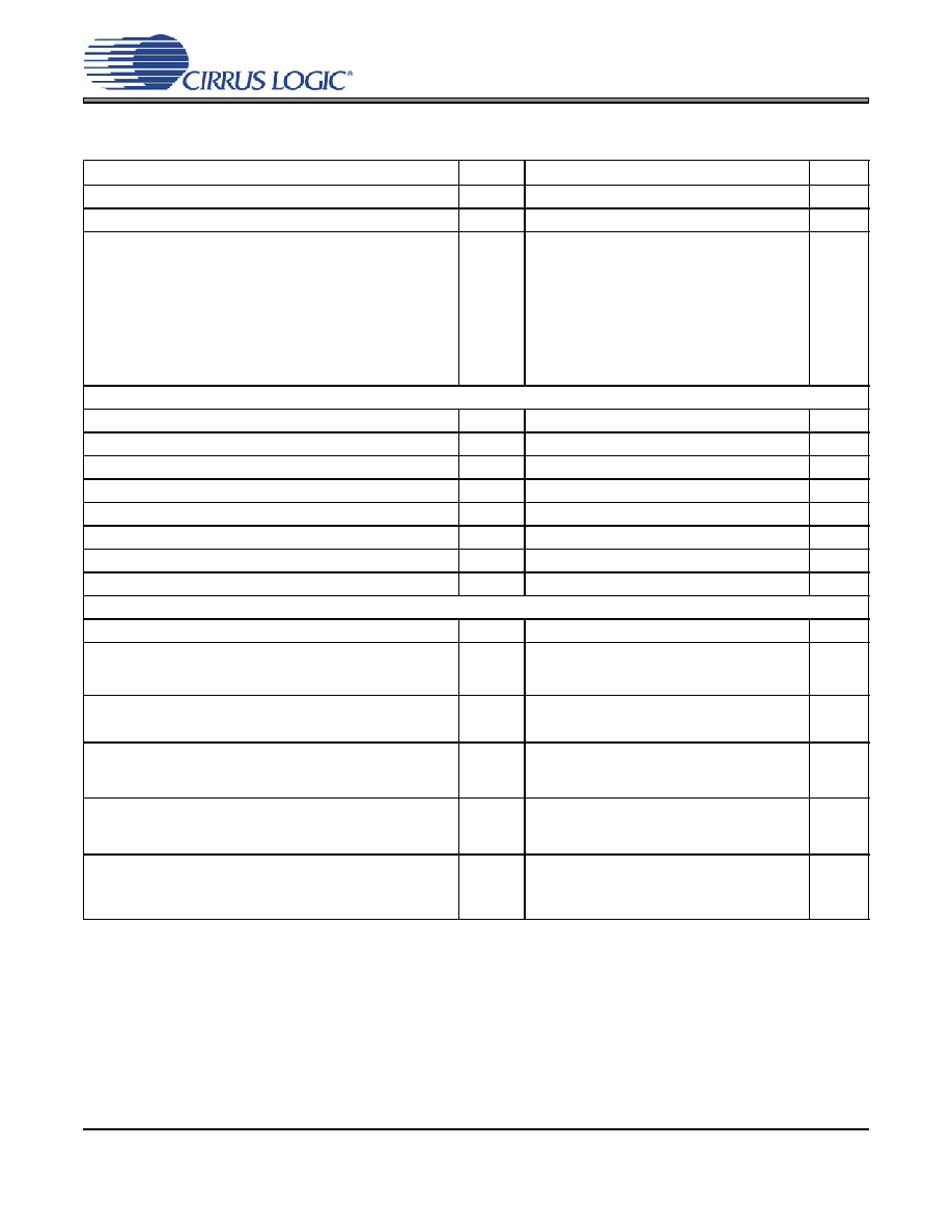
SWITCHING CHARACTERISTICS - SERIAL AUDIO INTERFACE
11. Not all sample rates are supported for all clock ratios. See table “Common Clock Frequencies” on
page 12 for supported ratios and frequencies.
12. In Internal SCLK Mode, the duty cycle must be 50%
±1/2 MCLK period.
13. The SCLK / LRCK ratio may be either 32, 48, 64, or 72. This ratio depends on data format and
MCLK/LRCK ratio. (See Figures 7-10)
Parameters
Symbol
Min
Typ
Max
Units
MCLK Frequency
0.512
-
50
MHz
MCLK Duty Cycle
45
-
55
%
Input Sample Rate
All MCLK/LRCK ratios combined
256x, 384x, 1024x
256x, 384x
512x, 768x
1152x
128x, 192x
64x, 96x
128x, 192x
Fs
2
84
42
30
50
100
168
216
54
134
67
34
108
216
kHz
External SCLK Mode
LRCK Duty Cycle (External SCLK only)
45
50
55
%
SCLK Pulse Width Low
tsclkl
20
-
ns
SCLK Pulse Width High
tsclkh
20
-
ns
SCLK Duty Cycle
45
50
55
%
SCLK rising to LRCK edge delay
tslrd
20
-
ns
SCLK rising to LRCK edge setup time
tslrs
20
-
ns
SDIN valid to SCLK rising setup time
tsdlrs
20
-
ns
SCLK rising to SDIN hold time
tsdh
20
-
ns
Internal SCLK Mode
LRCK Duty Cycle (Internal SCLK only)
-50
-
%
SCLK Period
tsclkw
--
ns
SCLK rising to LRCK edge
tsclkr
--
s
SDIN valid to SCLK rising setup time
tsdlrs
--
ns
SCLK rising to SDIN hold time
MCLK / LRCK =1152, 1024, 512, 256, 128, or 64
tsdh
--
ns
SCLK rising to SDIN hold time
MCLK / LRCK = 768, 384, 192, or 96
tsdh
--
ns
109
SCLK
----------------
tsclkw
2
------------------
109
512
Fs
----------------------10
+
109
512
Fs
----------------------15
+
109
384
Fs
----------------------15
+
发布紧急采购,3分钟左右您将得到回复。
相关PDF资料
CS4362-KQZ
IC DAC 6CH 114DB 192KHZ 48LQFP
CS4362A-DQZ
IC DAC 6CH 114DB 192KHZ 48-LQFP
CS4364-CQZR
IC DAC 103DB 24BIT 6CH 48-LQFP
CS4382A-DQZ
IC DAC 8CH 114DB 192KHZ 48-LQFP
CS4384-CQZR
IC DAC 8CH 103DB 192KHZ 48-LQFP
CS4385-DQZR
IC DAC 8CH 114DB 192KHZ 48-LQFP
CS4391A-KZZR
IC DAC 24BIT 192KHZ W/VC 20TSSOP
CS4392-KZZ
IC DAC 24BIT 192KHZ W/VC 20TSSOP
相关代理商/技术参数
CS4361-DZZ
制造商:CIRRUS 制造商全称:Cirrus Logic 功能描述:20-pin, 24-bit, 192 kHz, 6-channel D/A Converter
CS4362
制造商:CIRRUS 制造商全称:Cirrus Logic 功能描述:114 dB, 192 kHz 6-Channel D/A Converter
CS4362_04
制造商:CIRRUS 制造商全称:Cirrus Logic 功能描述:114 dB, 192 kHz 6-channel D/A Converter
CS4362_08
制造商:CIRRUS 制造商全称:Cirrus Logic 功能描述:114 dB, 192 kHz 6-Channel D/A Converter
CS4362A
制造商:CIRRUS 制造商全称:Cirrus Logic 功能描述:114 dB, 192 kHz 6-Channel D/A Converter
CS4362A_08
制造商:CIRRUS 制造商全称:Cirrus Logic 功能描述:114 dB, 192 kHz 6-Channel D/A Converter
CS4362A_09
制造商:CIRRUS 制造商全称:Cirrus Logic 功能描述:114 dB, 192 kHz 6-Channel D/A Converter
CS4362A-CQZ
功能描述:音频数/模转换器 IC 6-Ch DAC 24-Bit 192kHz 114dB w/DSD RoHS:否 制造商:Texas Instruments 转换器数量: 分辨率:16 bit 接口类型:I2S, UBS 转换速率: 信噪比:98 dB 工作电源电压:5 V DAC 输出端数量:2 工作温度范围:- 25 C to + 85 C 电源电流:23 mA 安装风格:SMD/SMT 封装 / 箱体:TQFP-32 封装:Reel